The IMU is an F´ passive component that collects data from the MPU6050 6-DoF Accelerometer and Gyro.
Introduction to MPU6050
Hardware Overview
I2C interface: The sensor reports data via an I2C interface.
I2C interface: The sensor reports data via an I2C interface.
Power management: The MPU6050 has several power modes. To begin collecting data, it must be "awakened" by writing 0 to the "Power Management 1" register at address 0x6B.
Accelerometer: Registers 0x3Bâ0x40 store the most recent accelerometer measurement as (x, y, z) in units of g. The full scale range can be set to ±2g, ±4g, ±8g, or ±16g. Each coordinate is a scaled 16-bit signed integer.
Gyroscope: Registers 0x43â0x48 store the most recent gyroscope measurement as (x, y, z) in deg/s. The range can be set to ±250, ±500, ±1000, or ±2000/s. Each coordinate is a scaled 16-bit signed integer.
Data sheet: For more details, see the manufacturer's data sheet .
Arduino Library
In the setup we installed the FastIMU library, which is essential for development of the IMU Component. The source code can be found in the FastIMU git repo.
You can review an example like Calibrated_sensor_output. This file has a .ino extension, which is used for Arduino-based projects. It's good practice to run the example first and then try to replicate the functionality in the F´ project.
You can also find a simpler version in read_accelereration_arduino/read_accelereration_arduino.ino.
Requirements
In the process of this tutorial we will have to satisfy the given requirements.
IMU Component
| Requirement ID | Description |
|---|---|
| Components-IMU-1 | The Components::Imu component shall power on from the beginning. |
| Components-IMU-2 | The Components::Imu component shall be able to communicate with the MPU6050 over I2C. |
| Components-IMU-3 | The Components::Imu component shall be able to produce telemetry and events for the MPU's I2C status. |
| Components-IMU-4 | The Components::Imu component shall produce telemetry of accelerometer data at 100Hz. |
| Components-IMU-5 | The Components::Imu component shall transmit data to other components from output port. |
Component Design
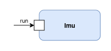
In the image above, we see the Component Diagram. The component has a run rate group input port to control the timing of data acquisition from the IMU and a MPU_data output port to get the data from the component.